Extrude and inset
These are two techniques that can help with adding mesh geometry.
| Action | Description |
|---|---|
E |
Extrude |
I |
Inset |
Exercise: extruding vertex to patch a hole
- Patch the large hole in the torus: select a single vertex and extrude it
into the middle of the hole (
E)
Tip
When extruding, as soon as you hit E, new vertices appear. They
appear whether or not you move them away from where they were extruded.
This means that if you do E, RMB to cancel, the extruded
vertices are directly on top of the original ones, even though it might
not look like it.
Either move/scale/rotate the new vertices, undo (Ctrl-Z), or
delete the vertices (X).
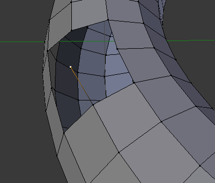
A single vertex extruded. Notice the new vertex (selected) already has an edge connecting it to the original vertex.
- Position the vertex – you may need to move around a bit to get a good
view, and possibly use wireframe mode (
Z).
Note
If we wanted to get perfect positioning, we’d have to do the math to figure out the X, Y, Z position based on the radius of the circle and then enter those coordinates in the Properties shelf.
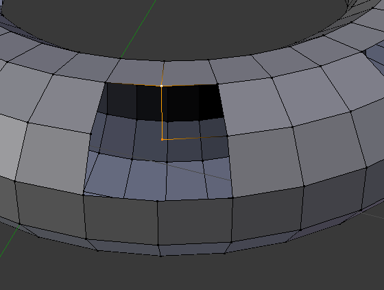
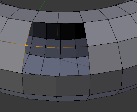
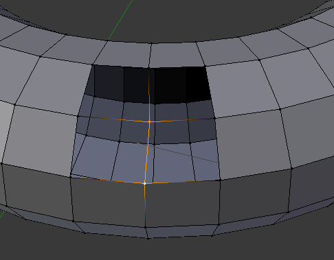
- Fill the hole by first creating the additional edges (
F), then filling the faces.
Exercise: extruding and insetting
To demonstrate extruding and insetting the goal here is to start with a cube and make the following object:
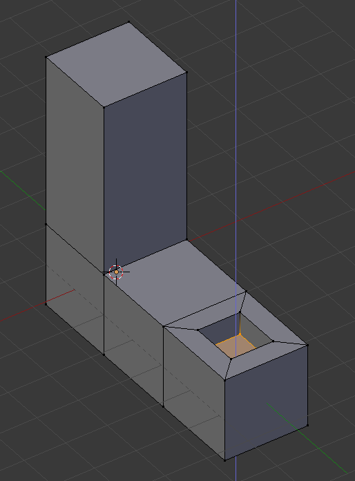
We’re aiming to make something like this from a cube.
- Back in Object mode, delete the torus.
- Snap the cursor to the center (0, 0, 0)
- Add a cube
- Switch to Edit Mode
- Select the top face and extrude upwards (
E,LMBto confirm,RMBto cancel)
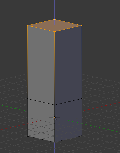
Extruding the top face
- Select one of the side faces and extrude it sideways to make the first part of the bottom of the “L” (see figure below)
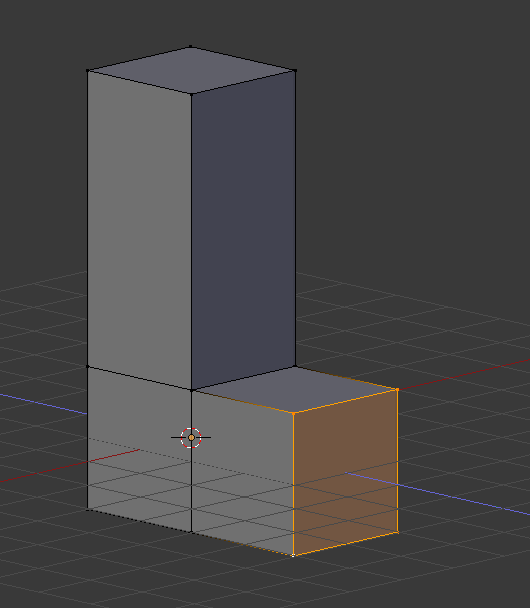
Extruding the side face
- With that face still selected, extrude again (see figure below)
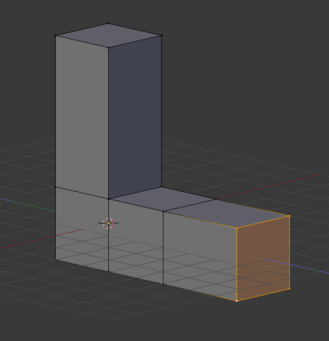
Extruding again
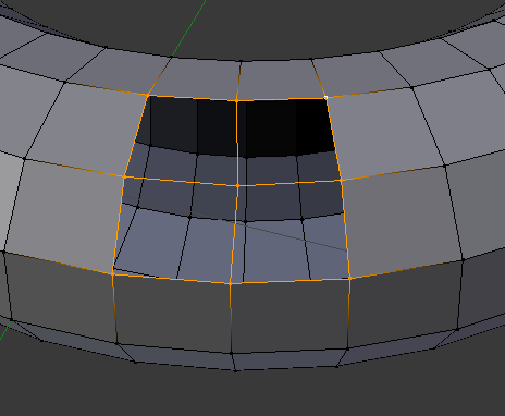
- Select the top face of the bottom of the “L” you just extruded and use
Ito inset the face a bit (see figure below).
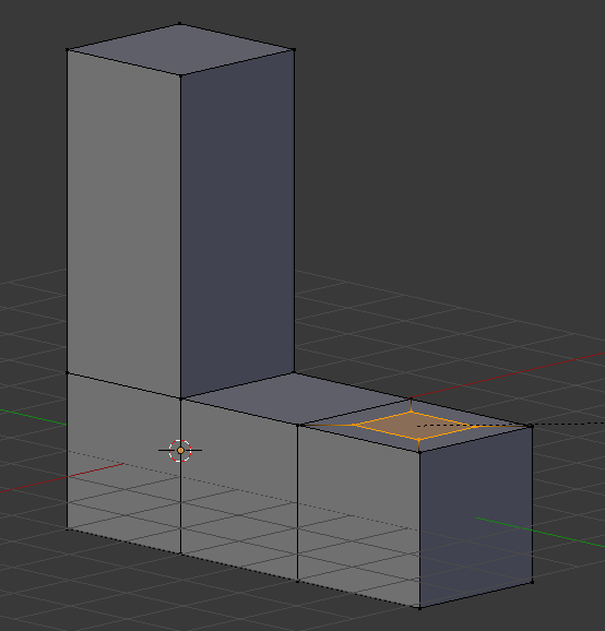
Insetting the top face
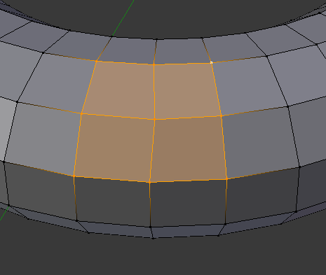
- With the inset face still selected, extrude that – but this time, move it down to create an indentation (see figure below)
Extruding the inset face downward
Note
Try experimenting – what happens if you move the inset face down directly instead of extruding it down? What happens if instead of two extrusions for the bottom leg of the “L” you just do 1?